TRC DIY #2 - Building Amplifier Kits
·
·
In today’s installment of TRC DIY, we will finally put the basic concepts covered in TRC DIY #1 to some practical use – by building a small amplifier kit. An amplifier is one of the fundamental building blocks of analog electronics, and the circuit in today’s example is a good representation of IC-based audio amplifiers in general.
Referring to the schematic diagram on slide 5, this is a type of “op-amp” circuit known as a “non-inverting amplifier” in which the difference between the voltages at the IC’s + and - pins is amplified.
The audio signal enters the IC at pin 4, is amplified, and appears at the output pin 1. Part of the output is fed back to the - input through a negative feedback network consisting of R1 and R3.
Negative feedback is an important concept in electronics and is used in audio amplifiers to limit amplification and reduce distortion. Note that C5 and C1 make the amount of feedback frequency-dependent. This technique is often used to alter the frequency response of an amplifier, such as in a phono-stage to achieve RIAA equalization.
Why Build Amplifier Kits?
Practically all speakers require a power amplifier to function. Integrated devices such as Bluetooth speakers contain an internal power amplifier. Thus, understanding amplifiers can allow us to build our own Bluetooth speakers, Hi-Fi systems, etc.

Tools and Instruments:
You will need a soldering iron, solder wire, steel wool or a sponge for keeping the iron clean, wire strippers, wire cutter, a de-soldering pump, some solid-core wire, and a digital multi-meter.

The Kits:
They consist of a printed circuit board, a bag of components, and an instruction sheet. A wide range is available from hobby shops or online stores. Single chip low voltage circuits are best for beginners.

Soldering:
The objective is to create a strong and permanent electrical connection by heating the contact points and applying solder, a fast-melting metal alloy that flows around the contacts and fuses them. When soldering, always work in a well-lit and ventilated area and take care not to accidentally touch the hot iron’s heated rod and tip.
The Circuit:
The first step in assembling a kit is to study the circuit schematic and PCB diagram. The kit in our example is a typical IC-based audio amplifier, and you will find similar circuits in all manner of audio equipment.
Starting Assembly:
Start by “tinning” or putting a bit of solder on your soldering iron tip and cleaning it. A shiny tip is essential for good results.
Most PCBs are marked with component names, making assembly easy. Feed the component leads through the holes and solder them to the pads on the other side. Finally, clip the excess leads.
As discussed in TRC DIY #1, pay attention to the polarity of electrolytic capacitors. On this PCB, the negative side is indicated by a solid line.

Install IC sockets and ICs in the correct orientation by paying attention to the half-moon tabs marked on the PCB, socket, and IC itself.

For external connections to volume controls, speakers, etc… strip off a bit of the wire’s insulation and insert the ends through the PCB as with the other components.
Volume Control:
A type of variable resistor known as a potentiometer is used to control the volume. The connections and their relation to the circuit symbol are shown.

AUX Input:
Cut an old AUX cable in half, strip off some of the outer insulation, then the three inner wires. There will be a black ground lead, and two coloured leads for the left and right channels. Since we are building a mono amplifier, the two leads can simply be tied together before being soldered onto the board.

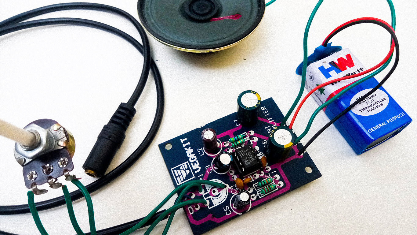
Power Supply:
The easiest way to power small amplifiers is by using a common 9-volt battery and cap connector. Solder the connector leads to the board, making sure that the black lead goes to the hole marked “- “ (or ground) on the PCB.

Speaker Connections:
Finally, solder some wires on the speaker terminals at one end, and onto the marked speaker connections on the PCB. You can now inspect your work, double-checking all connections, before attaching the battery and plugging in the AUX cable.

A low-power amplifier like this may not be too exciting on its own but can serve as the output stage of various DIY projects such as Bluetooth speakers. They are also good practice before you move on to more complex circuits such as high-power discrete amplifiers for Hi-Fi use.
✍ Written by: Santaji Shirke (@_electroidiot)
Read more: TRC DIY #1 – Getting Started with Audio Electronics
TRC DIY #3 – Building a Bluetooth Speaker System


Comments